Wednesday, 20 February 2019

50V PSU for SSPA


I decided that a bit of overkill / future proofing was needed for the PSU required for my SSPA.   There are many different PSU manufacturers and specs but I discovered that Kuhne sell the Meanwell units.  If they are good enough for DB6NT, it’s good enough for me!

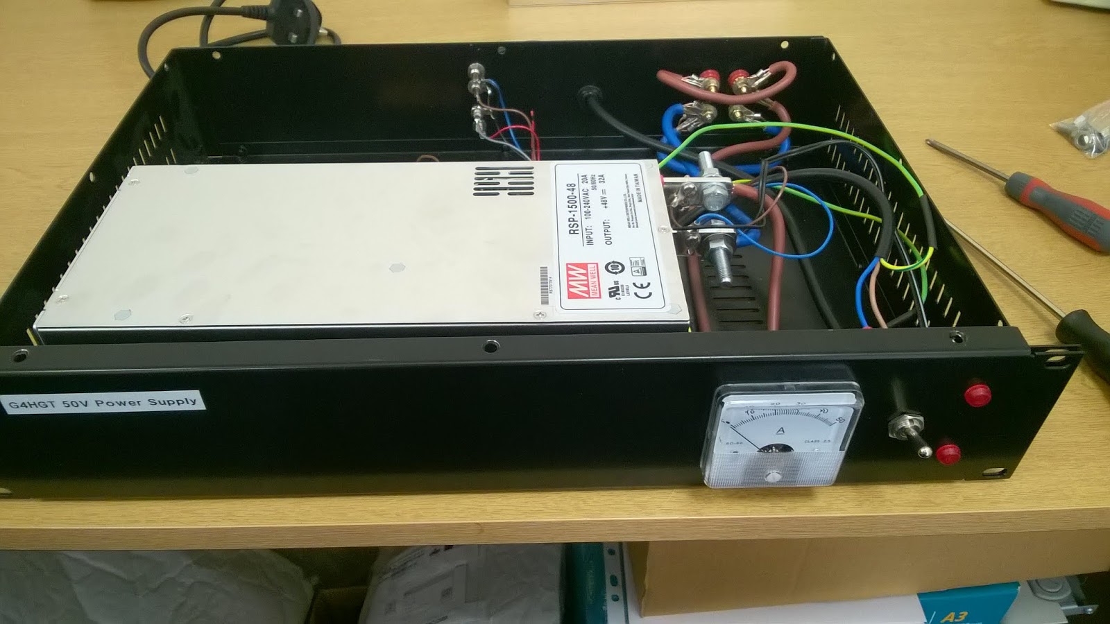
So I have used the RSP-1500-48V supply.  There’s nothing much to say about this part of the design; it just squeezes into a 2U 19” rack case, the lid needs a push to get the fixing screws in place and the psu is positioned under the case vent holes.  The 50V output is fed via a 50A fsd panel meter – I couldn’t find a 30A off-the-shelf meter and sorting out a beefy current shunt was going to take time so I just went for the 50A unit from Farnell.

The 50V terminals on the back panel are just 25A rated 4mm terminals and I use two red and two black in parallel.  The internal wiring is **mm **A rated cable used for house wiring, rather overkill but it won’t fail if the output was to be shorted together.

On the front panel are a couple of LEDs in red holders.  These are wired in series and in series with a pair of 20V Zener diodes then connected to the 50V supply.


The regulator / control circuitry Is built onto the Veroboard.  I need a 12V 500mA supply for the amplifier fan and a switchable 12V or so for the bias output.  These outputs are produced off the 50V supply.  The usual 7812 or LM317 type regulators are not designed for 50V inputs, so I used a series pass transistor to do a first reduce to 28V which might be a useful supply for 28V RF relays.  I used a *** transistor here and it needs to be on a heatsink (it is continuously dissipating 22V and 300mA).  If I ever use this supply for a 28V relay, it will probably need a bigger heatsink.  Then there are two regulators for fan and bias, again these are both on small heatsinks.  Finally, the bias is switched by a simple NPN controlled by the PTT input.


Noise from the 50V line

  
A few weeks ago, I had everything set up to do a few checks on the amplifier.  I discovered that my receiver noise floor rose by a few dB when I turned on the 50V supply.  This was with no antenna connected, the SSPA was to be checked into a dummy load.  When I’m out portable, everything is plugged together and then switched on so I simply hadn’t noticed this.  Although both my 50V psu and 12V psu were connected via earth terminals, I found the noise would appear when I connected the outer of the coax between my transverter and the SSPA.  This noise happened when the SSPA is in standby i.e. no current being drawn.  So this looked like a conducted emissions problem on the output side.  I found a basic generic filter design on an old Meanwell data sheet and a quick filter was constructed.

I had no idea about the spec of the toroid I found in my junk box so I wound 10 turns round it and measured the inductance – it turned out to be an Amidon FT-140-43.  Using fairly thick wire (2 x 1.5mm2) I could get 5+5 turns on the core, giving roughly 20uH.  For the capacitors, I thought about using low ESR units but didn’t have any to hand (and I don’t know if you can get them with 63V or 100V rating) so I just used what was to hand.  I also installed a small earth plate which is connected to mains as it enters the case; it is also connected to the PSU metalwork with a wide strap (UR43 braid).

Once the re-building was completed, I put my station back together, connected up the 50V supply and switched on – no noise!  Hopefully that should help pulling weak signals out, I will find out in a few weeks’ time.


Wednesday, 5 July 2017

70MHz QRO amplifier


For the UKAS contests in 2015-16, I was using a very old A200 amplifier which would only produce around 35W, ok for the AR section and absolutely fine running off the car battery.  However, once I had bought my generator, I was able to pull an unfinished project out of the cupboard – the SSPA.  I had bought this module from Hellenic RF Lab in Greece a few years earlier and put together the metalwork but just hadn’t got round to powering up.

The module is supplied fitted with an MRF6VP11 device, quite capable of the legal limit.  At full steam, the efficiency is around 80% - so 200W of heat to be dissipated.  I used the Marston Ultra-Fin heatsink fitted with the recommended Papst 3312 fan – this combination should have a thermal resistance of 0.08C/W implying a temperature rise of only 16C.  I have used four long screws through the heatsink to hold the fan in place.  Annoyingly, the fins of the heatsink flex when drilled so it looks a little untidy under the fan.  Don’t forget the finger guard on top of the fan.  The fan doesn’t seem to create a massive airflow (compared with fans used to blow a 4CX250) but all seems to work ok.


View inside amp


The output connector was screwed directly to the heatsink / groundplane and with the high RF currents, it seemed like a good idea to maintain this.    I’ve used a Perancea CFL3 case which has a fixed base and removable lid.  I made a cut-out in the bottom of the case so the heat spreader sits flush onto the heatsink.  Cutting out this rectangle was a bit painful with my limited tools (hacksaw and flat file) and I plan to use the version of the box with two lids for my next amplifier.   The output N connector is screwed directly to the end wall, then the heat spreader is screwed down to the heatsink.  When supplied, the input was also fitted with an N-connector which I removed and replaced with a short length of RG174 and a BNC connector for the input feed.

DC at 50V (and 20A) is fed in via a pair of chunky feed through capacitors and I’ve used phono connectors for the bias volts and fan 12V supplies.  The fan supply is fed back out on an SMC connector, it was easier to use a small screw-on connector to prevent the possibility of the cable loom pulling the wires off the fan.  I’ll write up the details of the main PSU in another blog entry.

The module arrived from Greece with the bias being fed by a power resistor from the 50V rail but I wanted to separate this out so I could turn the amplifier on and off using the PTT line.  I installed a little jumper link so I can select 50V or PTT.  The gate needs to be adjustable between 0V and 3V to set the standing current and there is a multi-turn potentiometer into the gate feed and this also allows the bias to be turned to zero for initial testing.

Testing

I was fortunate to be able to use work’s 50V, 20A, current limited power supply so I could do initial testing on the amp at a protected 2A and then turn everything up carefully.  The transistor data sheet indicates it should be biased to a few hundred mA and with less than a Watt of drive should give lots of power and indeed it did.  However, the power output started to fall off after a few seconds.  I realised the heat spreader was nice and warm but the heatsink was cold.  Although the spreader and heatsink were screwed together they were not connected thermally.  A quick layer of heatsink compound soon sorted that out and the amp is now temperature stable.  I also found that turning the standing current up to around 1A improved the gain significantly and probably did wonders for the linearity.


So after a quick tidy up and covers on, the amp was ready for use


Completed amplifier


Friday, 17 March 2017

Back again, time to catch up


March 2017   A little aside - back in May 2016 there was a technical article which I thought was rather poor with a 'construction' which I thought was a complete waste of time.  So much so, that I wrote to the editor and told him so. The editor said they were always looking for technical / practical articles so I offered an article based on my UKAC exploits.  I wrote the words, got up to speed with Express.sch for the circuit diagrams and took a few new pictures.  I submitted in November and to avoid any copyright issues, I haven't put anything on this blog since.

Three email reminders sent later, nothing from RadCom.  No acceptance, no decline, nothing.


So off we go again.


This is the normal operating set up for G4HGT/P with the KX3 sat on the control box, sat on the 144MHz transverter, all on the front seat of the car.

The transverter was built in the late 1980's with a BF981 front end.  Inside the pretty case is a good old diecast box providing a solid screen.  One day I really must take it into work and make some measurements, then decide if I need to bring it into the 21st century.  For now, the covers are staying firmly in place.


Inside the control box are 5 functional blocks:  12V regulators, RF switch, 28V inverter, sequencer and audio amps

The KX3 is a pretty expensive box so getting the polarity of the DC feed wrong and when rushing to get the station on-air could be disastrous.  So I've used a low-voltage dropout regulator to add a little protection.  The second regulator feeds the audio amplifiers.  This can also be switched off by the sequencer if I ever get RF breakthrough

RF switch - I need a sinple way to split the I/O of the KX3 into separate TX and RX lines. This box uses a G4JNT design pin-diode switch / attenuator from 1994.  The RF output from the KX3 at 28MHz is turned down to the minimum setting, roughly 100mW, then the potentiometer in the switch box sets the drive level into my transverters at around -10dBm

28V inverter - I have a 28V RF relay so i needed an inverter.  This little module was bought off eBay for less than a tenner - no point in trying to design my own.

Audio amps - probably a little overkill at the start, I could have just plugged my headphones into the KX3 but the audio out seemed a little low and with little LM380 amps available on eBay for pennies, I now have plenty of audio plus a combined audio if I ever need to peak the beam when outside the car

Sequencer - antenna relay switch, transverter switch, power amp switch and +12V feed for a preamp.  A stripped down version of a W1GHZ design


22 June:  So a week after writing my last entry, Giles Read, the RadCom technical editor, got back in touch and the article started moving in the right direction again.  It is now in for final tidy up and should be published in a couple of months.


Sunday, 22 May 2016

May/June - Ilkley Moor


So the 144 UKAC at the start of May had dreadful weather - gale force wind and lashing rain.  Putting the aerial up was fun, it's surprising how much pressure the wind puts on a 2 inch wide pole and the getting the pole into the clamp was rather scary!!  The clamp keeps the antenna fixed but it's not nice jumping out of the car and getting soaked to change antenna direction.  Still, the weather was no better elsewhere in the UK so the final result of third place was pleasing.

June's 144 UKAC was little better, the weather forecast was again very windy so I was prepared with ropes and pickets borrowed from G4ZAP stock.  This time, I couldn't even get 2 x 12' poles vertical - without the aerial!!  So had to drop back to 6' + 12' and ropes.  For this leg, Erik turned up in 93AD and naturally won with almost twice the points of second placed G0EAK.  I finished a reasonable 4th.


Then at the end of June was the second 70 UKAC and a chance to try out the new transverter feeding a 5ele Powabeam.  I couldn't get on top of the hill so operation was from the side of the road:


The little white dot to the right of the mast clamp is the moon.


First time on 4m for years so this was a bit of a learning curve but 4th place was a good result.

July - out with G4ZAP/G0VHF doing VHFNFD at Walton on the Naze for the first weekend - radioed out for the UKAC!!


4 x 12 ele, top at 60'


Wednesday, 18 May 2016

A New Site - IO93BV


So with a fixed transverter, April was a big improvement (92 contacts/32 multipliers/472k points/4th place, but it was time to find a new location for the summer.  I was also getting fed up with people asking me what I was doing in the pub car park.  

The best hill with a road in West Yorkshire is Ilkley Moor and there’s a few places to park a car at the side of the road with a good take off for most of the UK. 

The public road peaks at 380m but doesn’t go right to the top and there is a significant obstruction roughly 20m higher blocking ENE to ESE.  There's a gated track to a higher area at 390m which was originally claimed by police/fire services but their towers were removed a few years ago (thanks to Airwave).  A small comms station remains and is still gated/fenced off.  By a stroke of luck, it turned out that I knew the ‘right man’ through work and I was able to get access through the gate to the top.  The access track ends north of the existing building and mast so the site is slightly obstructed for a UKAC contest - but great for Denmark and Germany!


The view to the south/southeast from Ilkley Moor.  The boulders are supposed to prevent off-roaders churning up the ground.


Monday, 16 May 2016

Feb/March – building a 70MHz transverter


Back in the 1980s’ I was very active on 70MHz from home with a homebrew transverter (Jewell and Powis) feeding a single 4CX250 for legal limit power.  I had decided that since 144MHz UKAC was going nicely that I could fit in the four 70MHz contests, again probably just in the AL section.  So the transverter was found (in the loft again) but I quickly realised it only had 0.5W output – enough to drive the ‘250 but not enough for the contest.  Probably also a bit average on performance so I decided that a new transverter would be a good thing to bring me up to state of the art.  One quick email to G4DDK and a new unit was in the post.  Unfortunately, I didn’t have enough time to get everything working before the 31st of March but I was ready to go for June.


This is the G4DDK Anglian transverter in a 70MHz version with the 7W amplifier module on the rear panel.  The box and cabling dates from 1985, just needed a quick re-wire of the DC, add some SMA plugs and away it went.  For the record, 7W out with second and third harmonics >-66dBc - impressive.  The front end is some modern device so no need to worry about the system noise figure and 24dB gain.

Jan, Feb, March


January – first time out and just about everything went well until I jumped out of the car to turn the antenna and walked straight into the horizontal pole on the roof-rack!!  Fortunately the glasses survived although the log sheets have blood stains.  So first lesson – try things out close to home so you can get rescued (or call an ambulance) if necessary.  I ended up with 50 contacts, 28 multipliers and 10th position – not a bad start.

February / March – icy, slippy and cold.  I’ve always owned cold weather kit but make sure you are prepared.  It’s surprising how much cooler and windier it can be at the top of a hill so wear layers and waterproofs and a good warm hat.  Feb - 54 contacts, 26 multipliers, 7th place

March –  After February’s contest I was unhappy tuning speed of the IC706, you just can’t get up and down the band to search and pounce.  So I pulled the original HGT system out of the loft: IC735 and a homebrew transverter.  Side by side with the 706, receive performance on a weak GB3VHF beacon was very similar and a good 10W output available on transmit.  However, for the March contest, things were not quite right with horribly distorted locals being received.  I was able to get the transverter onto some good test kit at work revealing an oscillating input amplifier.  A quick re-build was required to calm down the BF981.  While sorting the preamp, I also noticed a 5V regulator was getting very hot and this was being caused by a 20 year old tantalum capacitor failing short circuit.  The regulator was preventing the tant from getting enough energy to go bang and was still outputting 5V.  Third lesson – check your kit properly at home before going out portable!!  March - 59/32/5th